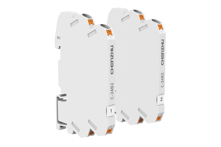
The electrical parameters of intrinsic isolated barrier need to match field instrument/control room instrument electrical interface. Basically, we could complete the simple selection through the following 5 selection elements.
Hazardous area signal | Safe area signal | Power supply | Number of channels(Input channels/output channels) | Install method |
Active 4-20mA | Active 4-20mA | Independentpower supply | 1/1 | DIN-rail mounting |
Passive 4-20mA | Passive 4-20mA | Loop power supply | 1/2 | Backplane mounting |
Voltage signal | Voltage signal | 2/2 | ||
Digital signal | Digital signal | 3/3 | ||
Transistor | Transistor | 4/4 | ||
Pulse voltage signal | Pulse voltage signal | |||
Communication signal | Communication signal | |||
Communication signal | ||||
Special specification | ||||
This is the first one.
This is the last one.
 English
 한국어
한국어 français
 Deutsch
 Español
 italiano
 русский
 português
 العربية
 tiếng việt
 čeština


